Power factor correction circuit diagram Inside the capacitor bank panel: power factor correction, calculation Automatic power factor controller circuit using microcontroller
Power factor correction topologies - Electrical Engineering News and
Figure 2 from single-switch single-phase boost power factor correction Automatic power factor circuit diagram Automatic power factor correction circuit diagram
The circuit diagram of the single-phase power factor correction system
Designing a power factor correction circuitPower factor correction Pfc passive factor correction circuits smps input homemadePdf télécharger power factor correction circuit gratuit pdf.
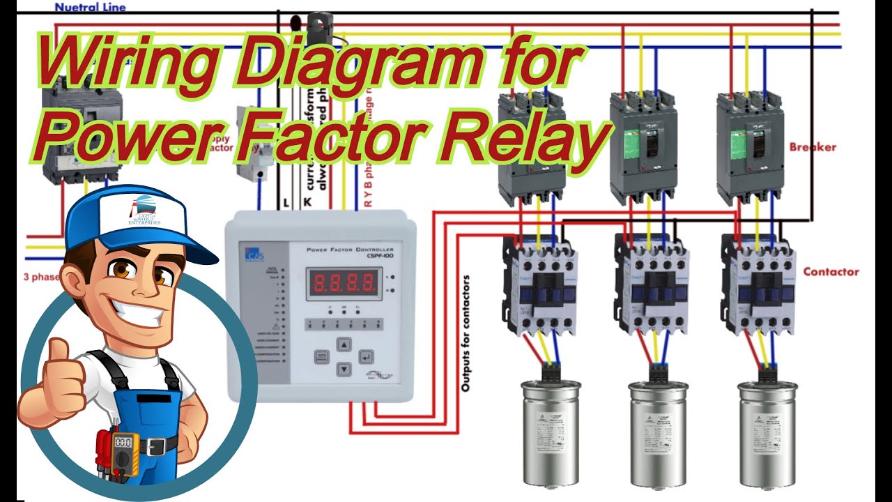
The-new-54b65-ncp1654bd65r2g-power-factor-correction-circuit.jpg2: circuit diagram of power factor improvement and controller Passive pfc power factor correctionControl wiring diagram of apfc panel.

Active power factor correction
Block diagram of power factor corrector circuit.Automatic power factor correction Power factor correction topologiesAutomatic power factor compensation for industrial power use to.
Power factor correction capacitor wiring diagramMicrocontroller based automatic power factor correction Patent ep1944856a1Pfc circuit diagram.

Automatic power factor correction using arduino
Power factor correction circuit diagramPower factor correction topologies ☑ automatic power factor correction using capacitorPower factor explained.
Correction implementationThe circuit design of the introduced power factor correction (pfc Relais gaan kapot van inrush current.Block diagram of automatic power factor correction.
Power factor correction circuit diagram
Power factor penalty diagram compensation minimize automatic industrial use electrosal blockFactor power using microcontroller controller automatic pic circuit diagram correction capacitor control apfc microcontrollerslab choose board Power factor correction circuit patentsCorrection factor power arduino automatic using electrosal diagram.
Factor correction poor explained correcting mindsetHow does dcfc work? Factor power correction circuitActive power factor correction circuit diagram.

Automatic factor power correction microcontroller diagram block project based
.
.


Patent EP1944856A1 - A power factor correction circuit - Google Patents

How does DCFC work? - Voltageace

Control Wiring Diagram Of Apfc Panel - Wiring Digital and Schematic

The circuit diagram of the single-phase power factor correction system

Power Factor Correction | Active Power Factor Correction | PFC Control

Home - keme-tec.com

Block Diagram of Power Factor Corrector Circuit. | Download Scientific